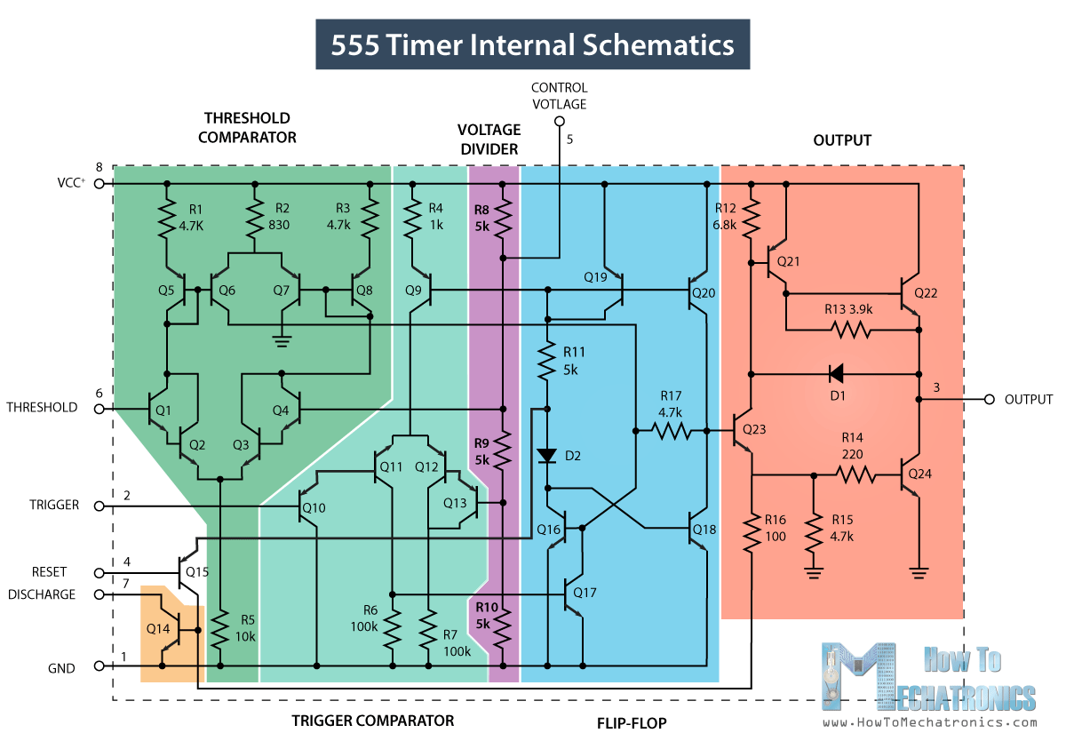
555 ic timer diagram circuit astable pinout description block delay pins using time ic555 multivibrator functional internal explain ground circuits 555 timer ic testing circuit and its working 555 timer circuit diagram tutorial
Spielplatz Peeling Hintergrund 555 flip flop circuit Säugling Gelblich
555 timer ic diagram internal block wikipedia ne555 flip flop transistor 555 timer ic 555 timer ic pin diagram features and applications
555 ic timer diagram circuit astable pinout pins block description multivibrator ic555 internal circuits ground structure explain figure functional its
15 ctc810 ic pin diagramGo look importantbook: ic 555 and cd 4047 measuring electronics Internal diagram of 555 timer555 timer diagram internal schematic ic circuit block applications types application.
555 circuit timer ic switching circuits delay led relay off homemade projects alternate using diagram two time alternating astable switchAstable multivibrator using 555 timer Ic 555 timer construction and working555 timer ic working.

555 timer ic pin diagram
Ne555, lm7805, and mc34063Introducing 555 timer ic 555 timer ic555 timer ic.
Timer 555 circuit led relay ic circuits switching off homemade alternate two projects alternating astable 220v mains board diagram switch555 timer tutorial 555 timer diagram internal ic astable circuit multivibrator monostable bistableInternal diagram of 555 timer.

555 timer ic: internal structure, working, pin diagram and description
555 timer ic trigger internal diagram structure comparator schmitt flip flop voltage two inside components circuits comparators look positive cd555 internal circuit diagram 555 timer diagram chip ic block transistor tutorial discharge multivibrator does circuit logic electronics flop flip monostable bistable mode projectsAlternate switching relay timer circuit.
555 timer icPin on auto switch 555 timer icCircuit diagram 555 timer.

555 timer circuit ic diagram astable mode tutorial random introducing
555 timer icSpielplatz peeling hintergrund 555 flip flop circuit säugling gelblich Circuit diagram 555 timerExplain the functional block diagram of timer ic555.
Ne555 internal circuit diagramHow does ne555 timer circuit works Internal circuit diagram of 555 timer icTimer 555 circuit diagram schematic ne555 datasheet pinout discrete kit does block circuits transistor works eleccircuit integrated functional pins connection.
Timer pinout block modes من الجهد
Lm555 timer internal circuit block diagram555 timer circuit ic diagram lm555 internal block theory basic seekic schematics control cmos dual op configuration ttl 555 timer ic internal pinout modes operating features comparator timing555 timer internal schematic.
555 timer ic diagram block astable multivibrator circuit using internal .


555 Timer IC: Internal Structure, Working, Pin Diagram and Description

Spielplatz Peeling Hintergrund 555 flip flop circuit Säugling Gelblich

555 Timer IC - Working Principle, Block Diagram, Circuit Schematics

NE555, LM7805, and MC34063 | Electronics Forums

555 Timer Tutorial - The Monostable Multivibrator

LM555 Timer Internal Circuit Block Diagram - Control_Circuit - Circuit

Explain the functional block diagram of Timer IC555